Multistage centrifugal pump Structure diagram Introduction
In general, multistage centrifugal pumps are several impeller installed on the same pump shaft, the outer side of the impeller is liquid diversion device and pump shell.
However, how are the impeller groups installed in or removed from the pump?
There are no more than two methods. One is to divide the pump body and the flow guide device horizontally along the axis of the pump shaft, making it into upper and lower parts.
Another method is to cut the pump body and liquid diversion device into several sections along the direction of the pump shaft between the impeller and the plane perpendicular to the pump shaft.
Multistage centrifugal pump Structure diagram
The structure of horizontal split type and subsection type multistage centrifugal pump is introduced.
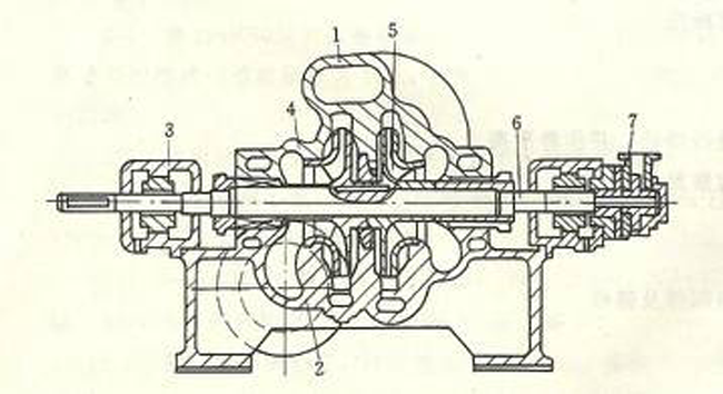
1. The structure diagram of horizontal multi-stage centrifugal pump is shown in FIG. 1.
This kind of pump adopts the volute pump body, each impeller’s periphery has corresponding volute chamber, is equivalent to several single-stage volute pump installed on the same shaft in series work, so it is also called volute multi-stage pump.
As the pump body is a horizontal split-type, the suction inlet and outlet are directly cast on the pump body, which is very convenient for maintenance. Only remove the pump cover to expose the entire rotor. When the rotor is overhauled, the whole rotor needs to be hoisted out without dismantling the connecting pipeline.
The impeller of the pump is usually arranged symmetrically with an even number, and most of the axial force is balanced, so there is no need to install the axial balancing device.
The flow range of the horizontal split-type multistage pump is 450 ~ 1500m’/h, and the maximum lift range is up to 1800mHz0.
Because of the symmetrical arrangement of the impeller and the cross-flow channel inside the pump shell, as shown in figure 2, it is larger in volume than the piecewise multistage pump of the same performance, with complex casting process, high positioning requirements for the pump cover and pump body, and difficult to seal the joint surface of the pump cover and pump body when the pressure is high.
2. The structure of sectional type multistage centrifugal pump
When the pressure is high, the sectional-type multistage centrifugal pump is usually used.
This kind of pump is a kind of vertical subdivision multistage pump, it has a front section, a tail section and several middle section composition, with four long rod bolt connection for a whole.
The number of impeller installed on the pump shaft represents the series of centrifugal pumps. Each impeller in the middle section is equipped with a guide wheel, which functions basically the same as the volute, mainly transforming kinetic energy into static pressure energy.
The impeller is usually single suction, and the suction population is oriented in one direction.
In order to balance the axial force, a balance plate is installed behind the end section and connected with the front entrance of the balance tube.
The rotor can run from left to right in the working process, balance the axial force of the impeller group by the thrust of the balance plate, and maintain the rotor near the balance position.
The two ends of the shaft are supported by bearings and placed on the bearing pedestal.
Low pressure boiler feed water pump conveying liquid temperature in 110 ℃ or so commonly, its structure and have the same general sectional multi-stage centrifugal pump, most common to each other.
For the feed pump of the medium-pressure boiler, because the working pressure and working temperature are higher than the low pressure, the requirements on the shaft sealing device are also higher. In addition to lubrication, some bearings are also cooled with circulating water.
In order to insulate, some of the pump in the outside of the rolled steel tube cover.
Some of the pumps are supported by a central support.
High pressure boiler feed water pump, conveying the temperature of the liquid in the 160-170 ℃, outlet pressure in more than 15 mpa.
Considering the influence of temperature change, the rotating part of the pump is mostly made of alloy with the same expansion coefficient.
The impeller is installed on the pump shaft, and the axial clearance of about 0.50mm is left at the end to prevent the impeller from being heated and expanded at the beginning of driving, and the impeller and the impeller will squeeze each other, causing tensile failure of the pump shaft.
The support of pump shaft adopts central support, so that the heat expansion of pump body after driving radiates everywhere with the pump axis as the center, and the unit can not be damaged, and the rotor is in the center at the end of the pump housing.