DF multistage corrosion resistant centrifugal pump – Mine Pump
DF multistage corrosion resistant centrifugal pump parameters:
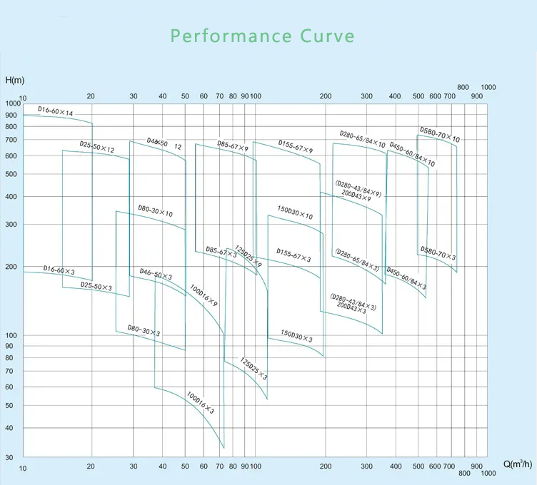
Flow: 7.5-840 m3/h
Head: 19-1140m
Outlet Dia: 40-300mm
Working Pressure: ≤ 6Mpa
Liquid Temp: 0℃- 105℃

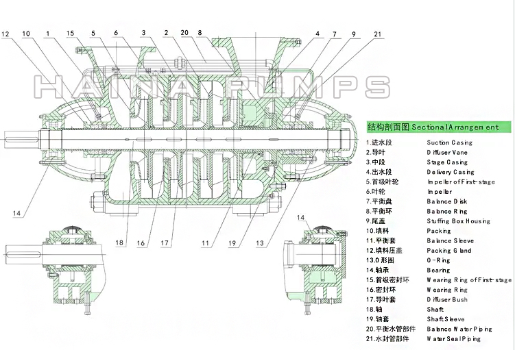
D/DF/DY/MD horizontal multistage centrifugal pump structure drawing

D/DF/DY/MD horizontal multistage centrifugal pump performance curve
DF multistage corrosion resistant centrifugal pump significance of model:
Example: D/ DF/ DY /MD 46-30 *4
D – multistage centrifugal cleaning pump
DF – multistage corrosion resistant centrifugal pump
DY – multistage centrifugal oil pump
MD – multistage wear-resisting centrifugal pump
46 – Design point flow is 46m3/h
30 – Design point single stage lift is 30m
4 – The series is level 4
Example: 100D/ DF/ DY /MD 16 * 3
100 – Pump suction diameter is 100mm
D – multistage centrifugal cleaning pump
DF — multistage corrosion resistant centrifugal pump
DY – multistage centrifugal oil pump
MD – multistage wear-resisting centrifugal pump
16 — Design point single stage lift 16m
3 – The series is 3 levels
DF multistage corrosion resistant centrifugal pump description:
DF multistage pump for corrosion-resistant mining This series of pump is horizontal single suction multistage segmented centrifugal pump, which adopts the hydraulic model of highly efficient energy-saving products recommended by the state. It has the advantages of high efficiency, wide performance range, safe and stable operation, low noise, long life, convenient installation and maintenance, etc.
This series pump is mainly used in mines, and its flow parts and easily damaged parts are made of corrosion-resistant materials, which can be used to transport neutral mine water and similar other sewage with solid particle content ≤ 15%, particle size ≤0.5mm and temperature below 80℃.In addition, the company can achieve the structure and function of this series of pumps according to user requirements.
DF multistage corrosion resistant centrifugal pump structural features:
This pump is a single shell, single suction, multistage minister section centrifugal pump structure, the pump inlet level, the export vertical upward specific structure is as follows:
1. Stator part
It is mainly composed of the front section, the middle section, the guide vane, the back section, the bearing frame and the balance chamber cover and other parts connected with the rod and the nut. The front section and the back side of the arm are fixed on the pump seat with bolts and nuts
2. Rotor components
Mainly by impeller, impeller baffle, balance baffle, balance plate and shaft sleeve parts with small round nut tight, fixed on the shaft with flat keys to prevent rotation. The whole rotor is supported on bearings at both ends. The rotor is connected directly to the motor by an elastic pin coupling.
In order to compensate for the expansion between the first stage and the balance baffle is equipped with a toothed pad, which should be replaced when the pump is repaired.
3. Balance mechanism
The pump adopts the hydraulic balancing device of the balance plate which can balance the axial force completely and automatically. The device consists of four parts: the balance plate, the balance plate, the balance sleeve and the balance baffle sleeve.